Analog Discovery 2™ Curve Tracer

User's Manual
Limited warranty is provided against manufacturing defects only.
The device is only to be used with a genuine Analog Discovery 2™ hardware, WaveForms™ software and accompanying WaveForms™ workspace. It’s also possible to use an experimental KS Curve Tracer app.
Links to the up-to-date documentation will be provided at the product page: https://knack.supply/product/ad2ct/
Please subscribe for updates to get notified of major changes.
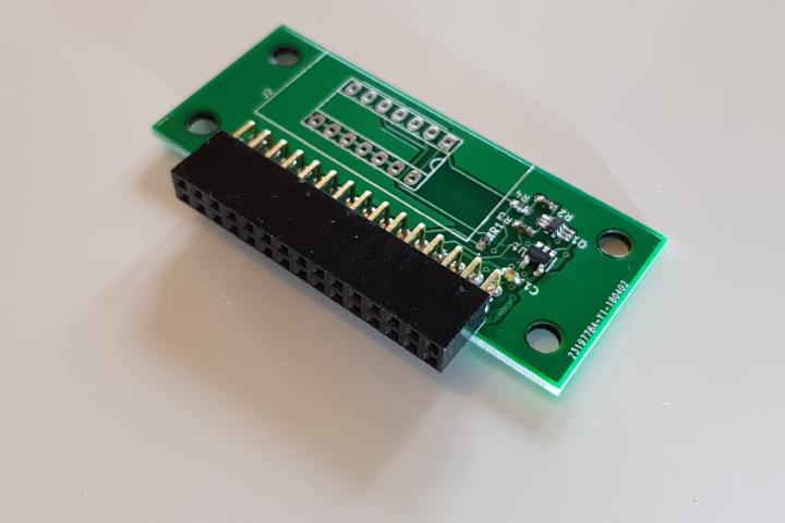
Plug in the add-on into Analog Discovery 2™ as shown:

Download the “.dwf3work” workspace file from https://github.com/knack-supply/ad2-curve-tracer.
Open it with WaveForms™ software.
Switch to Tabbed Interface in WaveForms™: Settings → Options → General → Instrument windows: Tabbed.
Insert the device under test, according to pinout shown in the next section.
Click the Play button on the Script tab in WaveForms.
Switch to the Scope tab.

Download the latest release.
Follow the KS Curve Tracer installation instructions
Select the device type. Use PN for diodes, NPN and PNP for BJTs.
Insert the device under test, according to pinout shown on the right pane.
Click the Trace button.

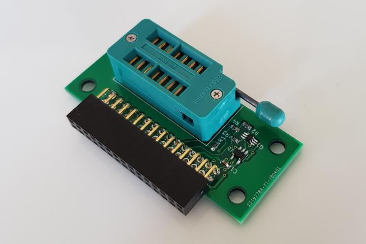
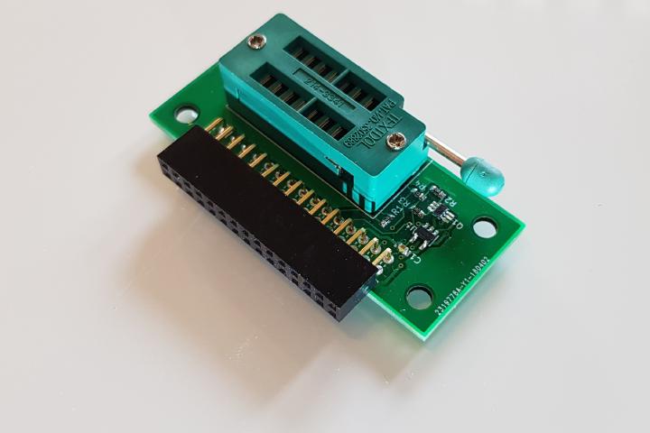
The IC socket has 2 rows: one for diodes and one for transistors.

Use the row closest to the board-to-board connection header. The pin closer to the centre of the board is anode, the rest are cathode.
Use the row furthest from the board-to-board connection header and closest to the edge of the board.
From the middle of the board to the edge:
Collector / Drain and Emitter / Source are specified for NPN BJTs and N-channel FETs. Swap Collector and Emitter For PNPs, Drain and Source P-channel FETs.
This product is certified open source hardware.
https://www.oshwa.org/cert/
You can find the source code at https://github.com/knack-supply/ad2-curve-tracer-hw and https://github.com/knack-supply/ad2-curve-tracer.
All components and substances used in manufacturing of this product are RoHS compliant.
The device doesn’t expose voltage higher than it’s host device, Analog Discovery 2, can provide. Usually it’s 10V between -5V and +5V rails, referenced to AD2’s device ground.
Current drive capability is limited to that of AD2’s adjustable dual-rail power supply and is further limited by design of the device itself to 60mA.
The device doesn’t radiate EM intentionally.
Unintended oscillations in the device could only theoretically occur at frequencies below 1.1MHz (typ.), there are no traces on the PCB which could act as transmitting antennae at those frequencies.